 Now Serving Canada
How Non-Penetrating Roof Guardrails Stay Secure Without Anchors (Wind, Friction, Ballast, Uplift)
A non-penetrating roof guardrail stays in place by using ballast (weight) and counterbalance geometry to create a restoring moment that resists tipping, while base friction and protective pads resist sliding—so the system meets required loads without penetrating the roof membrane. Wind, roof surface conditions, and layout choices all play major roles. This guide explains the real engineering principles, the failure modes that actually occur, and the information EDGE Fall Protection, LLC uses to configure safe, wind-aware systems for flat roofs across the U.S.
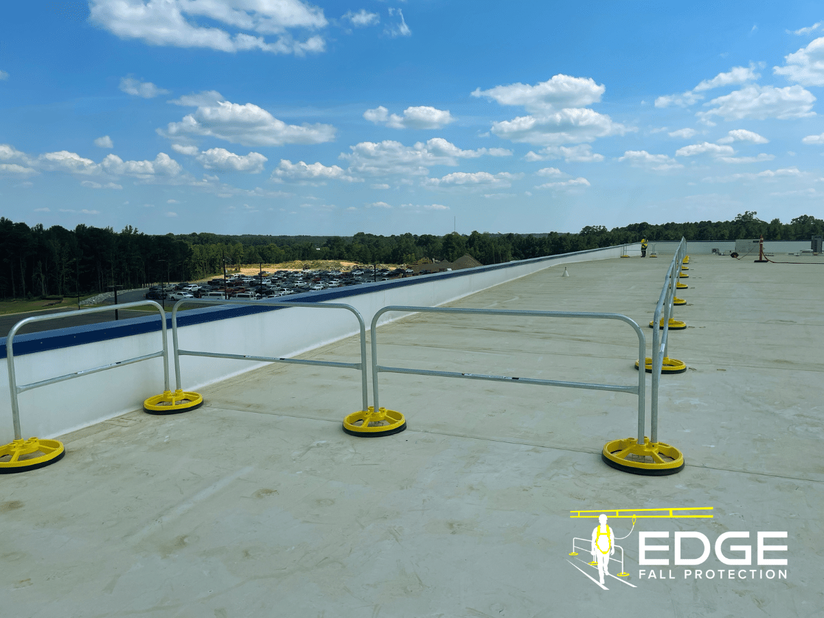
What Non-Penetrating Really Means (And What It Doesn’t)
A non-penetrating roof guardrail system is a free-standing barrier that provides fall protection without drilling into the roof, using ballasted bases and counterbalance geometry to resist tipping and sliding. The term “non-penetrating” describes the installation method. It does not mean “no planning required.”
These systems stabilize through three combined forces: weight pressing down on the roof, friction between base pads and the membrane, and geometric leverage (returns, setbacks, and base footprint). Non-penetrating guardrails products are designed to meet OSHA performance standards for preventing falls without creating holes that can leak or void warranties. They are not universal plug-and-play products.
Wind exposure, roof surface type, and edge conditions still matter. A system that works safely on a low building with parapets may not perform the same way on a taller building with open corners and smooth TPO. Non-penetrating does not mean unengineered—wind, roof surface friction, and end conditions determine whether an anchor-free guardrail stays put.
Guardrails are passive fall protection barriers. Workers do not interact with them the way they would with a personal fall arrest system. Unless a manufacturer explicitly engineers and labels a guardrail as an anchor point, you should not tie off to it. The design loads and certification requirements for barriers differ from those for fall arrest anchors.
OSHA requires fall protection at elevations of four feet in general industry and six feet in construction, according to OSHA fall protection guidelines. Guardrails offer a reliable way to meet these thresholds, particularly on flat roofs where workers may not recognize the hazard or may be tempted to skip harnesses during quick maintenance tasks.
The Short Answer
Non-penetrating guardrails stay secure by resisting three distinct failure modes: sliding, tipping, and uplift. Each mode requires a different engineering response, and safe configurations address all three.
- Resists tipping (overturning): Ballast weight creates a downward force. When combined with a horizontal lever arm (base width, setbacks, returns, or outriggers), that weight produces a restoring moment that counters the overturning moment caused by lateral wind loads or side impacts.
- Resists sliding: Friction depends on the normal force (how hard the base presses down) and the coefficient of friction between the pad and roof surface. Heavier bases and textured pads improve friction. Wet or icy membranes reduce it.
- Resists uplift: Wind flowing over roof edges creates suction (negative pressure). This suction can reduce the effective weight pressing down, lowering friction and increasing the risk of movement. Higher wind zones, taller buildings, and corner areas require added ballast or layout strategies that counter uplift effects.
- Stability from continuity: Rails connected into runs distribute forces across multiple bases. Corners and returns change the system’s geometry and improve resistance to both tipping and sliding. Missing returns or open ends concentrate loads and reduce stability.
OSHA requires that the top rail withstand at least 200 pounds applied outward or downward, and the midrail must withstand 150 pounds, per OSHA 1910.29 and OSHA 1926.502. For roof guardrail systems, this performance requirement drives the entire design. Ballast is intentionally added weight that increases stability by increasing normal force (for friction) and restoring moment (against tipping).
Anchor-free guardrails stay secure because the system is designed so wind and side loads must overcome both friction (sliding) and a restoring moment (tipping)—and properly configured ballast makes that unlikely.
| Failure Mode | What Causes It | What Design Features Prevent It |
|---|---|---|
| Slide | Wind or side load exceeds friction between base and roof | Ballast weight, protective pads with high friction coefficient, and proper surface prep on a clean, dry roof |
| Tip (Overturn) | Overturning moment (force × height) exceeds restoring moment (ballast × lever arm) | Heavy bases, setback from roof edges, returns or outriggers to increase lever arm, and a closed-loop layout |
| Uplift | Wind suction reduces effective weight, lowering friction and increasing sliding risk | Additional ballast weights, engineered corner layouts, and limiting runs near high-suction zones |
Engineering Primer: The Forces That Try to Move a Free-Standing Guardrail
Think of the guardrail like a weighted sign stand. Wind tries to slide it and tip it. Your job is to understand the inputs that make the difference between a system that holds and one that walks across the roof.
Lateral wind load is the horizontal pressure wind exerts on the rails and posts. Higher buildings see stronger winds. Corners and edges see higher local pressures due to turbulence and flow acceleration. The taller the building and the more exposed the site (open terrain versus downtown), the higher the demand. We won’t quote specific ASCE 7 wind speed numbers here because those calculations require engineering input. The concept is simple: wind pushes sideways on the rail, creating a force at a height above the roof.
Overturning moment is the turning effect created when a lateral force acts at a height, trying to rotate the guardrail base toward the roof edge. If you push on a post three feet above the roof with 50 pounds of force, the overturning moment is roughly 50 pounds times three feet, or 150 foot-pounds. The base wants to pivot around its edge-side corner.
Restoring moment counters that tipping effect. Ballast weight acts downward through the center of gravity of the base. If the base footprint extends 12 inches back from the pivot point and weighs 100 pounds, the restoring moment is 100 pounds times one foot, or 100 foot-pounds. If the overturning moment exceeds the restoring moment, the system tips. Setbacks, returns, and base geometry all increase the lever arm and boost the restoring moment.
Sliding resistance comes from friction, which equals the coefficient of friction multiplied by the normal force (the weight pressing down). Wet or icy membranes reduce the effective coefficient. Smooth single-ply membranes (TPO, PVC) may have lower friction than rougher surfaces. Ballast increases the normal force, which increases friction. Protective pads can improve friction and protect the membrane, but dirt, algae, or moisture between the pad and roof can reduce it.
Uplift (suction) happens when wind flows over and around roof edges. Negative pressure tries to pull objects upward. This reduces the effective weight pressing down, which reduces friction. Lower friction means the same wind force can now slide the guardrail. Uplift is highest at corners and near edges. Taller buildings and open exposures amplify the effect.
Why corners matter: Edge and corner regions see higher suction and turbulence. A straight run in the middle of a roof experiences lower demand than an open-ended run near a corner. Returns (perpendicular rail segments at open ends) are not cosmetic. They add lever arm, close the geometry, and stabilize the system against both tipping and sliding. Corners should be treated as higher-demand zones in any layout plan.
OSHA’s 200-pound top rail requirement, detailed in OSHA guardrail regulations, reflects real forces that workers might apply by leaning, stumbling, or pushing equipment. NIOSH testing has shown that properly configured systems can meet this requirement without roof penetrations. If a non-penetrating guardrail fails, it usually fails in one of three ways—sliding, tipping, or uplift-related loss of contact—so good designs address all three, not just weight.
The Four Stability Mechanisms
Non-penetrating systems rely on four interdependent mechanisms: ballast, friction, geometry (returns and continuity), and connection integrity. Each solves a different failure mode. Understanding them helps you evaluate vendor claims and ask the right questions.
Ballast (Weight)
Ballast increases both normal force (which boosts friction) and restoring moment (which resists tipping). Adding weight is the most direct way to improve stability. Where the weight sits matters as much as how much you add. A 50-pound weight placed at the edge-side of the base does little to increase the lever arm. A 50-pound weight extending the base footprint further from the edge significantly boosts the restoring moment.
Some manufacturers sell optional ballast weights that bolt or clamp onto bases to increase capacity in higher-wind regions. These are engineering accessories, not universal add-ons. The need for extra ballast depends on building height, wind zone, roof surface, and layout. Do not assume “more weight equals safer” without considering where it goes and whether the roof structure can handle concentrated loads without deflecting or ponding water.
Friction and Protective Pads
Protective pads serve two purposes: they protect the roof membrane from abrasion and punctures, and they can increase the coefficient of friction. The right pad material grips the membrane better than bare metal. Dirty or wet conditions can negate this benefit.
Friction is not a constant. A clean, dry TPO membrane in summer behaves differently than the same membrane covered in morning dew or coated with dust from a nearby HVAC unit. Ice changes everything. Plan surface prep and post-storm inspections as part of the system’s long-term performance, not as optional extras.
Geometry: Returns, Outriggers, and Closed Loops
A return (also called an outrigger) is a perpendicular guardrail segment at an open end that increases the system’s lever arm and improves resistance to tipping and sliding. Open ends are vulnerable. A straight run with no returns relies entirely on base weight and friction. Wind can catch the end like a lever and create a much larger overturning moment than it would on a closed loop.
Returns add stability by extending the footprint of the base group and changing the pivot geometry. They also block wind from acting on the open end as efficiently. Corners benefit from returns in both directions, creating an L-shape that distributes loads across more bases.
In anchor-free guardrails, layout is part of the engineering: returns, corners, and rail continuity can matter as much as the base weight. Do not treat corner configurations as optional. Missing returns is one of the most common real-world failure factors reported after wind events.
Continuity and Connection Integrity
Connected rails distribute loads. If one section experiences a lateral force, adjacent sections share it through the rail connection. Locking pins, set screws, and positive locking mechanisms keep rails from separating under stress. Loose connections allow rails to flex independently, concentrating loads and reducing overall stability.
Inspect connections after installation and after any roof work or storm. A missing pin can turn a stable run into a collection of individual, unstable segments. Consistent assembly practices and periodic checks keep the system performing as designed.
Competitor Context
Systems like the Kee Guard® Safety Guardrail System use a counterbalance approach and have established market presence. EDGE Fall Protection helps customers evaluate options and select the right approach for their roof conditions, wind exposure, and access requirements. Regardless of brand, the stability principles remain the same. Ask vendors how their system addresses sliding, tipping, and uplift—and whether their recommendations account for your corner zones and roof surface type.
EDGE’s AccuFit free standing railing represents one approach to ballasted guardrail design, engineered for a range of flat-roof applications. The key is matching the system to the site, not forcing the site to fit a generic product.
Wind and Uplift: What Changes on Real Roofs
Wind is not uniform. Edge and corner zones see higher suction and turbulence. Parapets can reduce direct exposure but do not eliminate suction on the roof deck. Guardrail systems near corners or on tall buildings face higher demands than systems on low buildings with interior setbacks.
Wind Pressure and Exposure
Wind pressure increases with height and decreases with obstruction. A guardrail on a 10-foot building surrounded by trees experiences less demand than one on a 60-foot building in an open industrial park. Exposure categories (open terrain, suburban, urban) affect design wind speeds. Engineers use these inputs to calculate expected loads.
Parapets create a barrier that can reduce wind hitting the rail directly. They do not stop suction acting on the roof deck. In fact, parapets can create local turbulence zones right behind them. Do not assume a parapet makes wind irrelevant. It shifts where and how wind acts, but it does not eliminate the load.
Uplift and Its Effect on Friction
Wind uplift (suction) is negative pressure created by airflow over roof edges that can pull upward on roof-level objects, reducing contact force and friction. Lower normal force means lower friction. The same lateral wind force that a system could resist in calm conditions might now cause sliding because the base is effectively lighter.
Corner zones typically see the highest uplift. Long straight runs with open ends can act like sails. Ice-covered or wet membranes compound the problem by lowering the coefficient of friction at the same time uplift reduces normal force.
When to Consider Added Ballast
Added ballast makes sense in several scenarios. Higher-wind regions (coastal zones, tornado-prone areas) increase baseline demand. Taller buildings see stronger winds and more uplift. Roof corner runs face elevated local pressures. Long straight runs with open ends lack the stabilizing geometry of closed loops. Smooth or low-friction surfaces (new TPO, polished metal) reduce sliding resistance.
If your project fits multiple categories, a wind evaluation is not optional. EDGE provides this service to ensure the recommended configuration handles the actual conditions, not just the catalog ratings.
Setback Considerations
Placing the system further from the edge can reduce overturning demand and improve stability. Some manufacturers specify minimum setback distances. These are not suggestions. They reflect the design assumptions used to calculate capacity. Installing a guardrail right at the roof edge when the manufacturer calls for a 12-inch setback changes the lever arm and can compromise performance. Other companies, such as EDGE recommends an 18” offset for added safety.
Setback also affects OSHA compliance. If the setback creates an unprotected zone between the guardrail and the edge, additional measures (warning lines, restricted access) may be required. Balance engineering stability with coverage requirements.
What an Engineer Will Ask For
Expect questions about building height, roof plan (including parapet height and edge details), exposure type (open terrain versus city), roof slope, intended rail layout, and whether the system will remain up year-round or be seasonal. If there are hatches, skylights, or equipment platforms, those matter too. The safest way to think about wind is this: corners and open ends are the controlling cases, so any anchor-free guardrail should be evaluated for those zones—not just the middle of a straight run.
EDGE offers engineering review and PE stamp services to formalize recommendations and provide documentation for inspectors and auditors.
Wind Readiness Checklist
- Roof height above grade
- Parapet present and parapet height
- Corner runs or open-ended straight runs
- Exposure classification (open field, suburban, urban)
- Roof surface type and condition
- Expected seasonal ice or wet conditions
- Number and location of open ends
- Gates, hatches, or skylight openings in the layout
- Setback constraints from equipment or property lines
- Storm inspection and maintenance plan
Roof Surface Friction and Membrane Protection
Friction is not a constant. Wet membranes, dust, and algae can change it overnight. Surface preparation and ongoing inspection determine whether friction remains high enough to prevent sliding.
Surface Prep Basics
Remove loose gravel, dust, and debris before placing bases. Place bases on sound substrate, not over damaged or ponding areas. Confirm the membrane is clean and dry. Any contamination between the pad and membrane reduces friction. Some roofing contractors leave cutoffs or fastener debris scattered after work. A single piece of foam under a pad can create a pivot point or low-friction zone.
Membrane Types and Friction Tendencies
Single-ply membranes (TPO, PVC, EPDM) tend to be smoother than built-up roofing (BUR) or gravel surfaces. Smooth surfaces generally have lower coefficients of friction. New membranes can be slicker than aged ones. Coatings applied to extend roof life can change surface texture and friction properties.
BUR and gravel roofs are typically rougher, which can improve friction. They may also be uneven, making level base placement more difficult. Gravel can migrate, creating localized high or low spots under bases. Do not assume gravel equals high friction. Loose stone on top of a smooth membrane underneath may not provide the grip you expect.
Heat and Adhesion Misconceptions
Some pad materials can soften or stick in heat if not designed for roofing contact. This is not a feature. Adhesion that works in summer can fail in winter, and pads that stick can damage membranes when removed. Do not use adhesives to “improve” a non-penetrating system unless the manufacturer explicitly allows it. Adhesives turn a removable system into a semi-permanent one and can void roof warranties.
Drainage and Ponding
Bases and pads should not dam water. Ponding around guardrail bases creates several problems: it adds weight the roof structure was not designed to support, it keeps membranes wet (lowering friction), and it can hide damage or migration. Design layouts to avoid blocking drain paths. Inspect after heavy rain to confirm no ponding has developed.
Seasonal Conditions
Frost and ice reduce friction dramatically. A system that performs well in summer may slide in winter if ice forms under the pads. Plan storm-season checks and consider temporary removal or enhanced ballast strategies when appropriate. Some facilities remove non-penetrating systems during hurricane season or winter and reinstall them when conditions improve. This works if access is infrequent and the removal/reinstall process is documented and controlled.
On smooth single-ply membranes, sliding can govern before tipping, so friction and surface preparation are as important as ballast weight.
| Roof Type | Common Surface Issue | Installation Prep | Recommended Protective Interface | Red Flags to Stop and Reassess |
|---|---|---|---|---|
| TPO | Smooth surface that can become slick when wet | Clean and dry the surface thoroughly, removing dust and debris before installation | Textured non-slip pads specifically designed for TPO roofs | Ponding water, visible membrane damage, or ice on the roof |
| PVC | Smooth surface similar to TPO | Clean and dry the surface, and confirm there are no coating compatibility issues | Textured pads rated for safe contact with PVC membranes | Coatings that soften in heat or any ponding water |
| EPDM | Can be smooth or textured depending on roof age and condition | Clean the surface and inspect for algae, moss, or other buildup | Pads that are compatible with EPDM and free from petroleum-based materials | Algae growth, wet conditions, or signs of cracking in the membrane |
| BUR (Built-Up Roof) | Rough surface that may include gravel or aggregate | Create a level surface and remove loose gravel beneath all base locations | Reinforced pads built to handle uneven roof surfaces | Soft spots, ponding water, or loose ballast stone |
| Gravel-Surfaced | Uneven surface where gravel can shift or migrate | Compact or clear gravel beneath pads and confirm the substrate below is solid | Rigid base pads or plates that help distribute load evenly | Deep gravel concealing membrane damage or shifting stones under load |
EDGE evaluates roof surface compatibility as part of the system recommendation process. We also discuss galvanized vs powder-coated finishes for bases and rails, as some coatings perform better in corrosive environments or high-moisture conditions. Surface contact accessories matter as much as the guardrail itself when friction is a limiting factor.
OSHA Compliance: What the Guardrail Must Do
OSHA cares about performance: height, strength, and safe surfaces. The regulation does not specify anchors versus a non-penetrating design. It specifies what the installed system must withstand.
Top Rail Height and Strength
The top rail must be 42 inches (±3 inches) above the walking surface, per OSHA 1910.29 and OSHA 1926.502. That is the compliance range: 39 to 45 inches. The top rail must withstand at least 200 pounds applied outward or downward at any point along the rail. This load represents a worker leaning, stumbling, or pushing equipment.
The midrail (or equivalent intermediate barrier) must withstand at least 150 pounds. These are minimum requirements. Systems can exceed them, and many do. The point is that non-penetrating systems must meet these thresholds through ballast, geometry, and continuity, not through fasteners. For more detail on compliance thresholds, see guardrail requirements.
Fall Protection Thresholds
OSHA requires fall protection at four feet in general industry and six feet in construction, according to OSHA fall protection guidelines. Rooftops almost always exceed these thresholds. Passive guardrails reduce reliance on worker behavior. A personal fall arrest system requires the worker to inspect, don, and connect the equipment correctly every time. A guardrail is there whether the worker thinks about it or not.
Guardrails Versus Anchors
Do not treat a guardrail as a tie-off point unless it is specifically engineered, labeled, and approved for that purpose. An OSHA-compliant guardrail (performance definition) is a barrier with required height and strength (including a 200-pound top-rail load requirement) designed to prevent workers from reaching a fall hazard. An anchor or lifeline must meet different design loads typically 5,000 pounds for fall arrest or engineered by a qualified person (like a certified safety professional or a licensed engineer) with a 2:1 safety factor, and must be certified and labeled as such. Tying off to a non-rated guardrail can cause the system to fail and the worker to fall.
Falling Object Protection: Toeboards
If tools, materials, or debris could fall from the roof and strike someone below, OSHA may require toeboards (a vertical barrier along the bottom of the guardrail, typically four inches high). Toeboards prevent objects from rolling or sliding off the edge. They do not add meaningful structural support to the guardrail itself. For guidance on when they are needed, see when to use toeboards.
OSHA requires guardrails to meet strength and height criteria, so non-penetrating systems must be engineered to resist real-world loads—especially wind—without relying on roof penetrations. The burden is on the installer to confirm the complete system (bases, ballast, layout, pads, connections) meets the performance requirement, not just to install a product that claims compliance in a brochure.
System Options and When to Choose Each
The right roof edge protection depends on roof type, access frequency, and wind exposure. Non-penetrating ballasted guardrails are one option. Other approaches may be better depending on the building and hazard. Our full guide to product-specific roof guardrails can be read here.
Non-Penetrating (Ballasted) Guardrail
Best for membrane roofs where penetrations are undesirable (warranty concerns, leak risk, or difficult-to-flash substrates). Ballasted systems protect the membrane and can be repositioned or removed without patching holes. They require wind evaluation and layout planning. Corners, open ends, and roof surface condition all matter. If your roof warranty, membrane integrity, or leak risk matters, a non-penetrating guardrail is often the most defensible first option—provided the wind and roof surface are evaluated.
EDGE offers several non-penetrating options. The folding guardrail option works for roofs where visibility or aesthetics matter, or where access is occasional and the rail can be folded down between visits.
Parapet Clamping
When parapets are present and structurally sound, clamping systems attach to the parapet wall rather than resting on the roof deck. This avoids membrane penetrations and reduces the footprint on the roof. Parapets must be able to handle the lateral loads without cracking or pulling away. EDGE’s parapet clamping rail system provides an engineered solution for this application. Parapet clamps still need review to confirm the wall construction and height are appropriate.
Metal Roof (Standing Seam or Corrugated)
Metal roofs often use clamps that attach to seams or specialized bases that sit in valleys without penetrating panels. These solutions avoid membrane concerns but introduce compatibility questions with panel profiles and fastener pullout. Warranty implications vary by panel manufacturer. EDGE’s metal roof guardrail addresses standing seam and corrugated applications with systems designed to grip seams or sit securely without drilling.
Warning Lines (Limited Scenarios)
Warning lines are cost-effective for certain work zones where access is controlled and workers are trained. They do not provide the same physical barrier as guardrails. OSHA allows warning lines in specific low-slope roofing work scenarios, but they come with strict rules about setback distances, worker training, and safety monitors. Guardrails are preferable in most cases because they are passive and do not rely on worker compliance. They are a great option when equipment is not within 15’ from the leading edge and can significantly reduce the overall costs of the project while providing a clear “do not cross” demarcation
EDGE Positioning and Consultative Approach
EDGE provides multiple options: non-penetrating ballasted systems, parapet clamps, metal roof solutions, and specialized systems for roof hatch guardrail installations, skylight protection, and HVAC and chiller protection. The goal is to align the solution to OSHA requirements and site constraints, not force-fit a single product.
Systems like the Kee Guard® Safety Guardrail System represent established counterbalance designs in the market. EDGE’s consultative approach means we help you select the right system and configuration regardless of brand, then provide the engineering review and layout guidance to ensure it performs as intended.
| Option | Roof Impact | Wind Considerations | Install Complexity | Best For | EDGE Solution Link |
|---|---|---|---|---|---|
| Non-penetrating ballasted | No penetrations; membrane contact only | Requires wind and uplift evaluation, especially in corner zones | Moderate; layout and ballast planning are required | Membrane roofs with warranty concerns | AccuFit system |
| Parapet clamp | No roof deck contact; clamps directly to parapet | Lower uplift concern, but the parapet must be able to handle the load | Low; quick to install when parapet conditions are suitable | Buildings with structurally sound parapets | Parapet clamp rail |
| Metal roof clamps | No panel penetration; uses seam or valley clamps | Clamp integrity matters in wind, with panel pullout risk needing evaluation | Moderate; clamp type must match the panel profile | Standing seam or corrugated metal roofs | Metal roof guardrail |
| Warning lines | Minimal impact; uses stakes or weights with a low-profile setup | Not designed to resist impact; intended as an awareness tool only | Low; simple layout and quick setup | Controlled work zones with trained workers and monitors | Enduring warning line |
What Engineers Ask For: The Intake Checklist
If you want a guardrail that stays put in wind, you need the same inputs an engineer uses. An engineering intake checklist is the set of site inputs (roof type, height, exposure, layout, and use) needed to evaluate whether a non-penetrating guardrail configuration will meet safety and wind demands.
The checklist below represents the information EDGE collects before recommending a system. If you cannot answer these questions, you cannot confidently claim an anchor-free guardrail is wind-ready for your roof.
Project Basics
- Site ZIP code or state (determines wind zone and environmental factors)
- Building use (office, warehouse, manufacturing, school, hospital, etc.)
- Access frequency (daily, weekly, seasonal, emergency-only)
- Who works on the roof (maintenance staff, contractors, HVAC techs)
Roof Geometry
- Roof height above grade
- Roof slope (flat, low-slope, or pitched; if sloped, what degree)
- Multi-level roof or single deck
- Parapet present; if yes, parapet height above deck
- Edge conditions (open, parapet, penthouse, equipment screens)
- Setback constraints (property lines, mechanical clearances, skylights)
Roof Surface
- Membrane type (TPO, PVC, EPDM, BUR, modified bitumen, gravel)
- Ballast stone or aggregate present on surface
- Coatings or sealants applied to membrane
- Typical wet or icy conditions (climate, drainage issues, ponding)
- Drainage paths and scupper locations
Wind Context
- Exposure classification (open terrain, suburban, urban/downtown)
- Corner runs or long open-ended straight runs
- Hurricane-prone region or tornado alley designation
- System intended use (seasonal, permanent year-round)
Layout Plan
- Total linear footage of guardrail required
- Number of corners and direction changes
- Gate or access point locations
- Ladder or hatch locations requiring clearance
- Equipment platforms, HVAC units, or skylights in layout area
Operations
- Inspection cadence (who checks the system and how often)
- Post-storm inspection plan
- Responsible party for reassembly verification if system is removed and reinstalled
EDGE provides a downloadable intake worksheet (Non-Penetrating Guardrail Wind & Roof Intake Worksheet) with fields for each of these items. Fill it out, attach a roof plan and photos if available, and submit it to the EDGE engineering team for a configuration recommendation.
Installation and Inspection: How to Keep Non-Penetrating Systems Secure Over Time
Most stability problems show up after weather, roof work, or partial reassembly. Installation quality and ongoing inspection determine whether the system performs as designed or gradually degrades.
Pre-Install
Confirm the roof surface is sound. Remove loose debris, gravel, and cutoffs. Verify placement setbacks per system instructions and layout plan. Do not deviate from the approved layout. A guardrail placed six inches closer to the edge than specified changes the lever arm and can reduce stability.
Assembly
Ensure rails are fully seated in posts and bases. Engage all pins, set screws, or locking mechanisms. Verify corners and returns are installed per layout. Do not skip end returns to save a few dollars or a few minutes. Missing returns is a common real-world failure factor.
Check that bases are level and stable. Rocking bases indicate uneven substrate or improper pad placement. Fix it before workers depend on the system.
After Storms
Walk the line after high winds, heavy rain, or snow load events. Confirm bases did not migrate or shift. Re-check all connections and verify rails remain seated. Look for pad damage, membrane scuffing, or ponding around bases. Document findings and correct any issues immediately.
A post-storm inspection is a documented check of base position, connections, and roof contact surfaces after high winds to confirm the guardrail remains stable and compliant. Keep a simple log with date, inspector name, and pass/fail for each section. This becomes part of your due diligence record.
Seasonal Maintenance
Check for corrosion, coating damage, and component wear. Confirm no ponding has developed due to base placement. Verify toeboards (if installed) remain secure and in place. Clean pads and membrane contact surfaces as needed to maintain friction.
Some facilities perform a full system check in spring and fall. Others inspect after every major roof access event. The right cadence depends on access frequency, climate, and risk tolerance.
Documentation
Keep an inspection log for EHS and compliance audits. Record installation date, layout plan reference, inspection dates, findings, and corrective actions. This demonstrates responsible management and supports OSHA compliance documentation. EDGE provides an equipment safety checklist template that can be adapted for guardrail systems.
NIOSH research notes installation efficiency differences between products. One commercial system installed 32% quicker than job-built configurations (25.6 minutes versus 37.9 minutes). Faster installation can improve consistency and reduce errors, but only if the installer follows the manufacturer’s instructions exactly. Speed without accuracy is a risk, not a benefit.
A non-penetrating guardrail is only as secure as its last complete, verified assembly. Missing returns or loose connections can undo the benefits of ballast and friction. Inspection is not optional. It is part of the design.
“Most people hear ’non-penetrating’ and think it means ‘just add weight and you’re done.’ It doesn’t. Weight in the wrong place won’t save you when a corner run catches a gust at the right angle. Ballast, friction, and geometry have to work together, and the place where that system either holds or doesn’t is almost always a corner or an open end. That’s not a detail. That’s the design.”
— Michael McCarty, President / Founder, EDGE Fall Protection
Frequently Asked Questions
How does a non-penetrating guardrail stay secure without anchors?
A non-penetrating guardrail stays secure without anchors by using ballasted bases and counterbalance geometry to resist tipping, plus friction between the base/pads and roof surface to resist sliding. The system is designed so that lateral wind loads and side impacts must overcome both friction (which resists sliding) and a restoring moment (which resists tipping). Properly configured ballast makes that unlikely, provided the roof surface is prepared, the layout includes returns at open ends, and the wind exposure has been evaluated.
The key is understanding that sliding, tipping, and uplift are distinct failure modes. Weight alone does not guarantee stability. Where the weight sits, how it interacts with the roof surface, and how the rails are connected all contribute to performance. Follow the manufacturer’s layout guidance, include returns at corners and open ends, and confirm the system is appropriate for your building height and wind zone.
How do non-penetrating roof guardrail systems stay secure in wind?
In wind, secure non-penetrating systems rely on a wind-rated layout (returns, corners, continuity) and sufficient ballast so lateral loads cannot overcome restoring moment and friction. Wind creates both horizontal pressure (trying to slide and tip the rail) and vertical suction (trying to reduce contact force). Corners and open ends typically see the highest demands, so those zones control the design.
Systems stay secure by distributing wind loads across multiple connected bases, using returns to increase the lever arm against tipping, and adding ballast weight (standard or supplemental) to maintain adequate restoring moment and friction even when uplift reduces the effective weight. The configuration matters as much as the product. A system that works on a low building may not work on a tall building with the same product if the layout and ballast are not adjusted.
Are non-penetrating roof guardrails OSHA compliant?
Non-penetrating roof guardrails can be OSHA compliant if the complete installed system meets OSHA height and load requirements, including a 42-inch top rail (±3 inches) and a 200-pound top-rail strength requirement. Compliance depends on configuration and installation, not on product category or marketing claims.
OSHA does not specify anchored versus non-penetrating design. It specifies performance. The installed system (bases, ballast, layout, connections, pads) must withstand the required loads. A system that meets the requirement in a test setup may not meet it in a real-world corner installation with inadequate ballast or missing returns. The burden is on the installer to confirm compliance through proper design, layout, and inspection.
Will a non-penetrating guardrail void my roof warranty?
Non-penetrating guardrails are often chosen specifically to protect roof warranties because they avoid membrane penetrations, but you should still confirm compatibility with your roof manufacturer and avoid practices that damage the membrane. Placing heavy bases on damaged or weak areas, creating ponding, or using adhesives not approved by the membrane manufacturer can void warranties even if no holes are drilled.
Use protective pads designed for your membrane type. Avoid dragging bases across the roof. Do not block drainage. Document the installation and inspection process so you can demonstrate responsible management if a warranty claim arises. EDGE works with facility teams to ensure guardrail installations align with roof warranty terms and manufacturer specifications.
How much does a non-penetrating roof guardrail system weigh?
The total weight varies by manufacturer and wind configuration, but most non-penetrating systems use heavy bases (30 to 70 pounds per base, depending on design) plus optional ballast weights (10 to 50 pounds each) to meet stability demands. The weight you need depends on building height, roof surface, wind zone, and layout (corner runs require more ballast than mid-run straight sections). The EDGE team recommends up to 104 pounds for their installed bases for an extra margin of error of increased safety.
Do not select a system based solely on base weight. Evaluate how the weight is distributed across the roof structure. Concentrated point loads can create depressions, ponding, or structural stress. Spread the load by using wider base pads or planning layout to avoid clustering bases in weak areas. Confirm the roof structure can handle the total distributed load before installation.
Do I need returns (outriggers) on a free-standing guardrail?
Many non-penetrating systems require returns (outriggers) at open ends because they improve stability by increasing the lever arm against tipping and sliding. Returns are not cosmetic or optional accessories. They change the guardrail’s geometry, add footprint to the base group, and help close the system into a more stable configuration.
Missing returns is a common real-world failure factor. Wind can catch an open end like a lever, creating a much larger overturning moment than it would on a closed loop with returns in place. If the manufacturer specifies returns, install them. If the layout plan shows returns, do not skip them to save time or money. This is both an engineering requirement and a manufacturer-instruction issue.
Can I tie off to a non-penetrating guardrail?
You should not tie off to a non-penetrating guardrail unless the system is explicitly engineered, labeled, and approved by the manufacturer as an anchor point for that purpose. Guardrails are passive barriers designed to prevent workers from reaching fall hazards. They meet OSHA’s 200-pound top-rail requirement, which is an outward/downward static load.
Fall arrest anchors must withstand dynamic loads (typically 5,000 pounds or more for personal fall arrest systems) and must be certified and labeled as anchors. Tying off to a non-rated guardrail can cause the system to fail, the worker to fall, and the employer to face citations. Use dedicated fall arrest anchors or lifelines for tie-off. Keep guardrails as passive barriers, not improvised anchor points.
What information does EDGE need to recommend a wind-appropriate non-penetrating guardrail?
EDGE needs your roof type, roof height, parapet and edge details, planned layout (including corners and open ends), and basic wind exposure context to recommend a configuration that stays secure without anchors. We also need to know access frequency, whether the system will be permanent or seasonal, and any equipment or skylight clearances that affect layout.
The downloadable intake worksheet provided earlier in this article lists all required fields. Send your roof photos, a plan view showing edge details and dimensions, and completed worksheet responses. EDGE’s engineering team will review the inputs and provide a layout recommendation, ballast guidance, and product selection tailored to your site conditions. This ensures the system meets OSHA requirements and stays stable in wind without guesswork.
Summary: Safety without Anchors
Non-penetrating roof guardrails stay secure by addressing three failure modes: sliding, tipping, and uplift. Ballast creates weight and a restoring moment. Friction resists lateral movement. Geometry (returns, corners, continuity) stabilizes the system against real-world wind and use conditions. Roof surface preparation and ongoing inspection keep friction high and connections tight.
OSHA compliance depends on the complete installed system meeting height and strength requirements, not on product claims alone. Wind evaluation is not optional for taller buildings, corner runs, or high-exposure sites. Corners and open ends control the design. If you cannot answer the intake checklist questions, you cannot confidently specify a wind-ready anchor-free guardrail.
EDGE Fall Protection provides the engineering review, layout planning, and product selection expertise to configure systems that protect workers and preserve roof warranties. We offer solutions for flat roofs, metal roofs, parapets, hatches, skylights, and equipment platforms. Our consultative approach means you get the right system for your site, not a forced-fit catalog product.
Get a wind-aware non-penetrating guardrail layout from EDGE. Share your roof type, height, parapet details, and access points. Send roof photos and a plan view if available. Our team will guide you to the right system and configuration, provide engineering documentation, and support installation and inspection planning. Contact EDGE Fall Protection to start the conversation.
References
- 1910.29 - Fall protection systems and falling object protection - Top rail height (42 inches ±3 inches), 200-pound top rail requirement, 150-pound midrail requirement
- 1926.502 - Fall protection systems criteria and practices - Construction guardrail criteria, 42-inch height, 200-pound strength requirement
- Fall Protection - Overview | Occupational Safety and Health Administration - Fall protection thresholds (4 feet general industry, 6 feet construction), fall statistics
- Evaluation of guardrail systems for preventing falls through roof and floor holes - NIOSH testing showing all 45 configurations met OSHA 200-pound requirement; installation time data
- Evaluation of guardrail systems for preventing falls through roof and floor holes (ScienceDirect) - All configurations passed OSHA testing; fall-through fatality and cost data