 Now Serving Canada

Non-Penetrating Guardrails for Reroof Projects: Low Parapets, Wind Security & Required Submittals
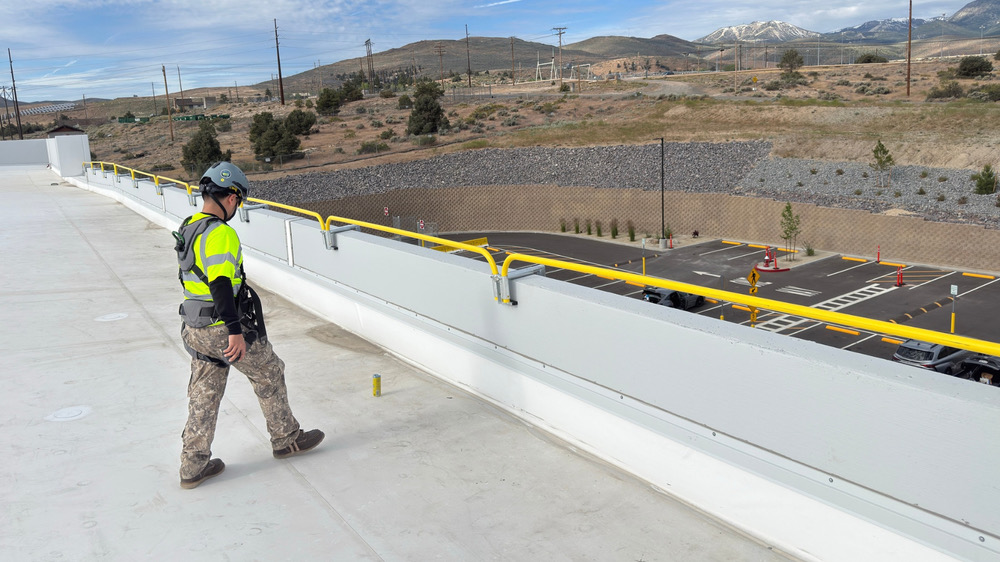
A non-penetrating roof guardrail system is a free-standing, ballasted perimeter barrier that meets OSHA guardrail performance requirements without fasteners or anchors through the roof membrane. For general contractors and roofing teams bidding 2026-2027 reroof projects, selecting the right system means matching wind exposure, parapet height, and roof load capacity to a configuration that will pass GC review. This guide walks you through feasibility checks, wind stability principles, low-parapet constraints, limited load capacity planning, and the actual drawings and calculations typically required to get your non-penetrating guardrail approved on the first submittal.
Quick Fit Check (Reroof Reality)
You’re bidding a 2026-2027 commercial reroof. The GC specification requires non-penetrating guardrail around the perimeter during tear-off and membrane replacement. The building has a low parapet (16 inches) and the project engineer flags that the existing roof deck may have limited load capacity. You need to know: Is a ballasted guardrail feasible? What information do you need before you call vendors?
Start by understanding that “non-penetrating” describes the installation method, not an exemption from engineering. A ballasted guardrail delivers its weight to the roof surface through base plates and friction pads. It must still meet OSHA guidelines for guardrail performance. Top rail height stays at 42 inches (plus or minus 3 inches). The system must withstand a 200-pound concentrated load at the top rail and a 150-pound load at the midrail, each applied in any outward or downward direction. These requirements come from OSHA 29 CFR 1926.502(b) and 29 CFR 1910.29(b). The method of attachment changes, but the performance bar remains the same.
Three constraints control your design choices. Wind governs stability at corners and open ends. Membrane friction affects how well bases resist sliding forces. Roof structural capacity determines whether the deck and insulation can support the total added weight and the concentrated pressure under each base plate. Any one of these can rule out a ballasted system or push you toward a lighter configuration with wider setbacks and extra returns.
When a parapet sits below 21 inches, it typically cannot replace the midrail requirement. You still need a midrail or equivalent intermediate protection. Wind suction near the edge intensifies when parapets are low or absent. Returns at terminations become structural components, not aesthetic choices. Most manufacturers specify minimum return lengths (often 5 feet) at corners and open ends to resist tipping and sliding. Skipping those returns can void the system’s engineering basis.
Before you pick up the phone, gather this information. You need roof plan dimensions, building height, parapet height at each edge, roof membrane type (TPO, PVC, EPDM, or other), deck construction (steel, concrete, wood), known structural limits (allowable psf if available), and the location of roof access points, drains, hatches, and equipment. If you cannot provide most of these inputs, expect the vendor to ask for a site visit or decline to quote. In reroof projects, the fastest way to get a non-penetrating guardrail approved is to submit a roof-specific layout plus engineering that verifies wind stability and roof load capacity, not just a product cut sheet.
Roofing remains one of the deadliest trades. According to the U.S. Bureau of Labor Statistics, roofers had the third-highest fatal work injury rate among selected occupations in 2024: 48.7 deaths per 100,000 full-time equivalent workers, with 104 deaths. In the roofing contractor industry, 96 of the 120 fatal work injuries in 2024 were falls, slips, or trips. The compliance lens is strict because the stakes are high.
| Input | Why It Matters | What to Provide in Submittal |
|---|---|---|
| Parapet height | Determines if parapet can act as midrail equivalent and affects wind pressure on rails | Measured height at each edge, note if variable |
| Building height / exposure | Controls wind velocity and corner-zone suction demand | Building height above grade, site exposure category if known |
| Membrane type and condition | Affects friction coefficient between pads and roof surface | Membrane manufacturer/type, note if new or existing, any slick coatings |
| Deck type and joist spacing | Influences local load capacity and deflection limits | Deck material (steel, concrete, wood), joist spacing, any known restrictions |
| Allowable load (psf) | Sets upper bound on total added dead load and base contact pressure | If available: design live load, roof dead load, any posted capacity limits |
How Non-Penetrating Roof Guardrails Stay Secure Without Anchors
A non-penetrating roof guardrail stays secure without anchors by resisting sliding, tipping, and uplift using ballast weight, high-friction roof pads, and stabilizing geometry (continuous runs and required returns at ends and corners). Wind security for non-penetrating guardrails is engineered by checking sliding resistance, overturning resistance, and corner-zone uplift, not by adding weight and hoping. To understand why, break stability into three failure modes.
Sliding occurs when horizontal wind or side loads overcome the static friction between the base pads and the roof surface. Friction force equals the normal force (the weight pressing down, which includes ballast) multiplied by the coefficient of friction. The normal force depends on how much ballast you place in or on each base. The coefficient of friction depends on the pad material, the roof membrane type, and surface conditions. Wet, icy, or dust-covered roofs reduce friction dramatically. EDGE’s engineered wind rating calculations assume wet-condition friction coefficients between the EPDM base pad and the roof of 0.4 for TPO, 0.5 for PVC, 0.6 for EPDM, and 0.8 for BUR or modified bitumen, and recommend friction testing to confirm them for each installation. Lower friction means you need more weight or better geometry to maintain the same sliding resistance.
Tipping (overturning) happens when a side load at the top rail creates a moment that rotates the base about its toe. Wind pushing on the rail exerts a horizontal force at roughly 42 inches above the roof. That force times the lever arm produces an overturning moment. The restoring moment comes from the base weight acting through its center of gravity plus any stabilizing effect from adjacent sections and returns. A wider base footprint and lower center of gravity improve resistance. Returns and continuous runs distribute loads across multiple bases, reducing the demand on any single post. Ballast is sized so the restoring moment exceeds the overturning moment by a factor of safety. EDGE’s engineered wind rating tables provide an inherent factor of safety of 1.67 against both sliding and overturning when compared with ultimate wind pressures.
Uplift reduces the effective normal force on bases near the roof edge. Wind flowing over a parapet or around a corner creates negative pressure (suction) on the roof surface. That suction effectively lifts the base, reducing the downward force and thus the available friction. In high wind and low-parapet conditions, corner zones experience the highest suction. Wind design methods account for this with pressure coefficients that depend on location on the building, and FEMA notes that the highest uplift loads occur at roof corners, followed by the roof perimeter and then the field of the roof. Uplift does not physically pull the guardrail off the roof in most cases, but it can reduce friction enough to allow sliding or tipping.
Returns are structural geometry, not aesthetics. A return is a perpendicular guardrail segment at an open end that increases the system’s stabilizing lever arm and helps the run resist tipping and sliding under wind or side load. Picture an L-shaped configuration at a corner. The two legs brace each other. A single straight run terminating at an open edge has no lateral restraint at the end. Wind can rotate it. Adding a 5-foot return transforms that end into a braced corner. Many manufacturers require returns at all terminations and specify minimum lengths (often 5 feet). Omitting them can void the wind rating.
You cannot tie off to a non-penetrating guardrail unless the manufacturer explicitly designs and labels it as an anchorage point. Guardrails meet barrier load requirements (200 lb top rail, 150 lb midrail). Personal fall arrest anchorages must support 5,000 pounds per worker attached, or be designed as part of a complete personal fall arrest system with a safety factor of at least two under the supervision of a qualified person (29 CFR 1926.502(d)(15)). EDGE’s engineering guide explains that these two functions have different design loads and certification requirements. Use the guardrail as a passive barrier. If workers need tie-off, install separate anchorages.
Corners and open ends govern the design. If a non-penetrating guardrail moves in wind, it almost always traces back to one of three issues: missing returns, insufficient corner-zone treatment, or reduced friction from wet, icy, or dirty roof conditions. Plan for returns. Verify corner configurations with the manufacturer. Include inspection triggers for weather events that degrade friction.
| Failure Mode | What Causes It | What Design Features Prevent It | What the Submittal Should Show |
|---|---|---|---|
| Sliding | Horizontal wind load exceeds friction between pads and roof | Ballast weight, high-friction pads, clean dry surface, returns for load sharing | Ballast quantities, pad friction coefficient assumption, surface prep notes |
| Tipping / Overturning | Wind moment at top rail rotates base about toe point | Wide base footprint, low center of gravity, ballast distribution, continuous runs, returns | Base dimensions, ballast location, connection method between sections, return details |
| Uplift (effective) | Wind suction near edges reduces normal force, lowering friction | Additional ballast at corners, setbacks to reduce exposure, returns to brace ends | Corner-zone ballast adjustments, setback dimensions, wind pressure assumptions |
Some manufacturers publish wind ratings for their systems. These ratings provide a useful reference point, but they apply only to the tested configuration, including exposure category, spacing, and return requirements. EDGE evaluates wind for the actual site conditions, not just the catalog ratings. Tall buildings, unusual exposure (coastal, ridge-top), or atypical layouts often require project-specific engineering beyond catalog values. Always ask whether the published rating applies to your site conditions.
Low Parapets During Reroof
A low parapet is a roof edge wall under 21 inches that generally does not replace the need for a midrail or equivalent intermediate member under OSHA guardrail criteria. Parapet height affects OSHA compliance, layout constraints, and which non-penetrating options make sense. If a parapet is under 21 inches, it generally cannot serve as an OSHA midrail equivalent, so the guardrail system still needs a midrail (or equivalent) and must be configured with setbacks and returns appropriate to wind and roof conditions.
When a parapet is at least 21 inches high, OSHA does not require a separate midrail or equivalent intermediate member (29 CFR 1910.29(b)(2), 1926.502(b)(2)). Verify that the top of the parapet is continuous, that openings are within OSHA limits, and that the overall system (parapet plus top rail) meets height and strength requirements. Under OSHA’s guardrail criteria, even if the parapet acts as a midrail substitute, you still need a compliant top rail and any required toeboards. The parapet does not eliminate the guardrail; it changes its configuration.
Parapets below 21 inches require a full guardrail with midrail. You install the system inside the parapet line or, if the parapet is very low, you may need to set the guardrail closer to the edge to keep workers from reaching over. Bump-outs or setback adjustments become necessary near roof hatches, scuppers, or equipment where sight lines to the edge are blocked.
No-parapet edges present the highest wind exposure. Without a parapet to deflect wind, corner zones and edges see full velocity pressure and higher suction. Returns and setbacks become critical. Some engineers recommend increasing ballast at corners or reducing the maximum run length between returns. The absence of a parapet also means more direct line-of-sight to the edge, which can improve worker awareness. Where tools or materials could fall on people below, OSHA requires falling-object protection such as toeboards.
A low parapet can reduce direct wind on the rails, but it does not eliminate corner-zone suction or the need to meet OSHA guardrail geometry and strength requirements. Plan for midrails. Document the parapet height on drawings. Show how the guardrail configuration addresses edge coverage and wind exposure. Include notes about bump-outs or equipment zones where the parapet may obstruct worker movement or visibility.
| Parapet Height Range | What It Can / Can't Replace | Typical Solutions | Submittal Notes |
|---|---|---|---|
| ≥ 21 inches | May substitute for midrail if continuous and meets opening limits | Top rail only (if parapet qualifies), verify OSHA compliance | Parapet height verification, opening schedule, top rail attachment or placement method |
| < 21 inches (low parapet) | Cannot replace midrail requirement | Full guardrail (top rail + midrail), setbacks as needed | Show midrail, note setback from parapet, corner and end treatments |
| No parapet | No intermediate protection | Full guardrail, increased corner ballast, shorter run limits, returns mandatory | Wind exposure assumptions, corner-zone treatment, return dimensions and spacing |
Visit parapet fall protection for additional strategies when parapets create layout or access challenges.
Limited Load Capacity Roofs
Non-penetrating does not mean “no structural review.” It means the load goes into the roof through weight and contact area. On load-limited roofs, the controlling check is often not OSHA’s 200-pound rail load; it’s whether the roof can safely support the guardrail base weight and contact pressure without crushing insulation or overstressing the deck. Older roofs, lightweight deck systems, and roofs with soft insulation can all limit what you can install.
Two load values matter. Total added dead load is the sum of all guardrail bases, rails, and ballast spread across the roof area. The total depends on configuration (base count, spacing, corners, and returns); each AccuFit base, for example, is a 104-pound cast iron unit. The total goes into the roof’s overall load budget. Localized contact pressure is the weight at each base divided by the base’s effective bearing area, often expressed in psf. A small base footprint concentrating heavy ballast can exceed local deck capacity or crush compressible insulation even when the average roof load remains acceptable.
Reroof projects introduce temporary complications. During tear-off, you may place guardrail bases on cover boards, plywood overlays, or partially stripped assemblies. New single-ply membranes are slick. Staged materials (bundles, tools, debris) cluster near edges. These conditions change friction assumptions and load distribution. Plan for friction to drop after membrane installation until surfaces weather or accumulate texture. Inspect bases after major material moves to confirm they have not shifted or settled into soft spots.
Insulation type controls deflection and bearing. Polyisocyanurate (polyiso) and extruded polystyrene (XPS) boards have different compressive strengths. Tapered insulation varies in thickness and thus stiffness. Wet insulation loses strength. If a base plate rests on saturated insulation during a storm, it can settle or punch through. Document insulation type and known compressive strength in your submittal. Flag any areas with known ponding or saturation history.
What the structural engineer will ask for: deck type (steel, concrete, wood), joist or beam spacing, existing roof live load design value, existing collateral loads (HVAC, screening), allowable psf for new equipment or added dead load, and any posted capacity restrictions. If the building lacks recent structural drawings, expect to provide a site inspection report or arrange for a structural review before the guardrail vendor can finalize the submittal.
When capacity is limited, consider these approaches. Use larger distribution pads or plates under each base to spread load over a wider area, reducing contact pressure. Relocate the guardrail line inward from the edge (increase setback) to place bases away from the most flexible deck zones or over stronger framing members. Select lighter modular systems with aluminum components instead of steel where code allows. If perimeter guardrail remains infeasible, discuss alternative controls (such as warning line systems combined with a safety monitoring system) with the GC, but only where OSHA permits and the contract allows substitutions.
Base contact pressure is the load delivered to the roof at the guardrail base divided by the base’s effective bearing area (often expressed in psf), which helps evaluate deck or insulation overstress risk. A 200-pound base on a 1-square-foot plate delivers 200 psf. Spread that same load over 2 square feet and you get 100 psf. Match base sizes to deck capacity.
| Common Roof Assembly | Limiting Factor | Submittal Documentation Needed |
|---|---|---|
| Steel deck with polyiso insulation | Insulation compressive strength, deck gage and span | Insulation thickness and type, deck gage, joist spacing, base plate dimensions |
| Concrete deck with rigid insulation | Concrete slab capacity at supports, insulation crushing | Slab thickness, span, insulation type, base contact area |
| Wood deck with low-slope framing | Decking deflection, joist capacity, point load at base locations | Decking material and thickness, joist size and spacing, base load distribution method |
For projects requiring professional engineer involvement, see PE stamps and engineering guidance to understand when and why a PE letter or sealed calculation set is requested.
Recommended Non-Penetrating Guardrail Options for 2026-2027 Reroof Projects
If your parapet is low and your roof capacity is uncertain, start with these rules of thumb. For typical commercial reroofs where the site’s design wind pressure (based on exposure category, railing height above ground, and design wind speed) falls within the system’s rated sliding and overturning capacity, choose a modular free-standing system like EDGE AccuFit. When you need temporary removal or reduced visual profile after project completion, consider a folding system like EDGE 360 Mobile Hide-a-Rail. If parapet geometry creates edge access or hatch coverage challenges, use manufacturer-approved accessories, bump-outs, and returns to maintain compliant perimeter coverage. When perimeter guardrail cannot meet structural limits, escalate to the GC and explore warning lines with a safety monitoring system (only where code and contract allow).
For reroof projects with low parapets and uncertain roof capacity, EDGE’s approach is to select a non-penetrating system and then engineer the layout and ballast strategy to the building’s wind exposure, corners, and structural limits so the submittal matches the site, not a generic catalog. That principle drives the options ranked below.
Option A: EDGE AccuFit Free Standing Safety Railing
Best all-around for reroof perimeter work. The AccuFit railing uses galvanized steel pipe and cast iron fittings on 104-pound cast iron bases with EPDM roof pads. You configure runs, corners, returns, and gates to match your roof plan. The 104-pound cast iron bases are the ballast, and EDGE’s engineered wind rating tables list the sliding and overturning capacity of each run length by roof surface, for use by the project engineer. Pads distribute load and protect the membrane. The system ships in sections for fast installation and easy relocation during phased tear-off.
AccuFit has been evaluated for wind on TPO, PVC, EPDM, BUR, and modified bitumen roofs. EDGE provides layout assistance and submittal-ready drawings that show setbacks, return locations, and ballast schedules. When the project requires a PE stamp, EDGE coordinates with licensed engineers to deliver site-specific calculations that address OSHA loads, wind stability, and roof capacity. This option fits commercial reroofs where you need compliant perimeter protection, predictable approval timelines, and minimal roof penetration risk.
Option B: EDGE 360 Mobile “Hide-a-Rail” Collapsible Guardrail
Best when visibility, aesthetics, or temporary folding is needed. The collapsible roof guardrail folds down when not in use, reducing sightlines and wind loads. This feature appeals to facilities where rooftop HVAC or equipment service continues during reroof phases and you need to restore unobstructed access after each work shift. The counterweighted bases remain in place; only the rails fold. You can deploy and stow sections without removing ballast.
The Hide-a-Rail system is ideal for buildings with strict aesthetic standards, frequent rooftop access by maintenance teams, or multi-phase projects where guardrails stay installed for months but must clear sightlines for inspections or events. Ballast and friction requirements match standard non-penetrating systems. Wind ratings and return rules apply when the rail is in the raised position.
Option C: Manufacturer-Approved Accessories for Low Parapet and Edge Challenges
When a low parapet blocks sight lines to hatches, equipment pads, or edge-mounted drains, you cannot simply skip coverage. Use approved bump-outs (short perpendicular sections that extend the guardrail line past obstructions), offset bases (move the base inward to clear parapet cap details), and intermediate posts (reduce span if midrail sag becomes an issue). Always verify with the manufacturer that accessories and non-standard configurations maintain the system’s wind rating and OSHA compliance. Document accessory placement and attachment in submittals.
Option D: Alternative Controls (When Perimeter Guardrail Is Not Feasible)
If the roof cannot support even a lightweight ballasted system, discuss fall protection hierarchy with the GC. For roofing work on low-slope roofs, OSHA 1926.501(b)(10) allows a warning line system combined with a guardrail, safety net, personal fall arrest, or safety monitoring system. The warning line must be at least 6 feet from the roof edge (1926.502(f)), and workers between the warning line and the edge must be protected by one of those systems. Personal fall arrest with engineered anchorages is another option. These alternatives require GC approval, competent person oversight, and often more complex safety plans. EDGE can design warning line layouts and anchor systems when perimeter guardrails are ruled out by structural limits, but expect longer approval cycles and stricter jobsite controls.
A ballasted guardrail is a non-penetrating system that uses counterweight bases and roof-safe pads to meet guardrail performance requirements without roof anchors. Choose the system that fits your constraints. Avoid these mistakes: removing returns to save cost, placing bases on debris or loose insulation, treating a guardrail as a tie-off point, ignoring corner zones, and submitting generic catalog pages instead of site-specific layouts.
| Option | Best For | Key Constraints | Typical Submittals Needed |
|---|---|---|---|
| AccuFit Free Standing | Most reroof perimeters, commercial buildings, predictable approval | Site wind pressure within rated capacity; standard membrane; moderate capacity | Roof plan, corner/return details, ballast schedule, wind/load calc summary |
| 360 Mobile Hide-a-Rail | Aesthetic needs, temporary visibility control, frequent access cycles | Same as AccuFit when raised; fold mechanism requires training | Same as AccuFit plus deployment/stowing procedure, maintenance notes |
| Accessories / Bump-outs | Low parapet sight-line issues, hatch coverage, edge equipment zones | Must maintain OSHA compliance and system wind rating | Accessory placement drawings, manufacturer approval letters, compliance notes |
| Warning Lines / Active Systems | When roof capacity cannot support any ballasted guardrail | Requires a paired system (e.g., safety monitor), competent person, GC approval, limited to low-slope and certain activities | Warning line layout, anchorage plan, safety procedure, competent person designation |
Wind Resistance Details That Win Submittals
Corners govern. Wind pressure and suction intensify at building corners and roof edges. Turbulence increases. Uplift is highest at roof corners, followed by the perimeter and then the field of the roof. Your submittal must show how you address corners explicitly. That means specifying return lengths, corner-zone ballast adjustments, and setback dimensions that match the assumptions in the system’s engineering.
Returns at terminations are mandatory in most non-penetrating systems. A return is a perpendicular guardrail segment at an open end that increases the system’s stabilizing lever arm and helps the run resist tipping and sliding under wind or side load. Typical minimum return length is 5 feet. Some manufacturers require returns at every termination (corners, gates, open ends). Others allow shorter runs or no returns in sheltered mid-run areas. Never assume. Check the manufacturer’s installation manual and published wind rating conditions. If you omit a required return, the system may fail inspection or move during a storm.
Setback is the horizontal distance from the roof edge to the guardrail line; it affects overturning leverage and wind stability, and it must match the assumptions used in the system’s engineering. A larger setback reduces wind exposure (the guardrail sits in a slightly lower velocity zone) and can reduce edge suction effects. A smaller setback places the guardrail closer to the edge, increases wind demand, and requires more ballast or stronger geometry. Manufacturers publish setback requirements (EDGE specifies bases at least 18 inches from the edge when no parapet is present) to ensure the guardrail still provides effective edge protection under OSHA. Installing closer to the edge than specified can invalidate wind assumptions. Installing farther than allowed can put workers outside the protected zone.
Toeboards prevent tools and materials from sliding off the roof. When objects could fall and strike someone below, OSHA requires falling-object protection such as toeboards, screens, a canopy, or barricades (29 CFR 1926.501(c), 1910.28(c)). A standard toeboard is at least 3.5 inches tall. Adding toeboards increases the wind area of the guardrail, which raises the overturning moment. Some systems include integrated toeboards in the base design. Others offer clip-on toeboard panels. When you add toeboards, verify that the ballast schedule accounts for the extra wind load. Document toeboard placement on drawings, especially at gates and access points where removable panels may be needed.
Membrane condition changes with weather. A clean, dry TPO roof in summer provides good friction. That same roof covered in frost, snow, or rain has less friction. Dust, leaves, and ponding water also reduce grip. Include inspection triggers in your submittal: post-storm checks, seasonal freeze-thaw reviews, and surface cleaning before and after major wind events. EDGE’s engineering guide recommends a documented post-storm inspection of base position, connections, and roof contact surfaces after high winds.
Manufacturer wind ratings provide a starting point. Each published rating applies only to the manufacturer’s tested configuration. Change the exposure category, increase building height, reduce return lengths, or install on a different membrane and the rating may no longer apply. Taller buildings, more open exposure categories (such as Exposure C or D under ASCE 7-16), and unusual roof geometries often require project-specific engineering beyond catalog values. Ask the vendor whether the published rating covers your site. If not, request a custom calculation.
| Wind-Risk Feature | Where It Matters Most | What to Show on Drawings | What to Verify in Calcs |
|---|---|---|---|
| Returns | Corners, open ends, gate terminations | Return length, orientation, connection method | Stabilizing moment contribution, load distribution to adjacent sections |
| Setback | All edges, especially high-exposure zones | Dimension from edge to guardrail line, note if variable | Wind velocity at setback location, effective pressure on rails |
| Corner ballast | Building corners, parapet corners, roof equipment corners | Ballast quantity per base at corners vs mid-run | Increased wind demand at corners, uplift reduction, sliding check |
| Toeboards | Edges where tools/materials are present, OSHA-required zones | Toeboard height, attachment, removable sections at gates | Added wind area, updated overturning moment, ballast adjustment if needed |
| Surface condition | All base locations, especially exposed or ponding-prone zones | Membrane type, surface prep notes, ponding or debris notes | Friction coefficient assumption, reduced friction case (wet/ice), inspection triggers |
Consult the guardrail selection guide for additional decision criteria when comparing systems and configurations for wind-exposed projects.
Typical Submittals Required (Drawings and Calculations)
Submittals get rejected when they’re generic. A typical GC submittal for a non-penetrating roof guardrail includes a roof plan layout, corner and return details, base and pad interface details, and an engineering package that checks OSHA rail loads, site wind demand, and roof load capacity (including base contact pressure and total added dead load). Reviewers ask three questions. Is it OSHA-compliant? Will it stay put in wind? Will the roof support it? Your submittal must answer all three with site-specific information.
Drawing Set (Typical)
Roof plan with guardrail line. Show the guardrail perimeter overlaid on a roof plan. Dimension setbacks from edges, parapet lines, and major roof features (hatches, drains, HVAC units, ladders, equipment pads). Identify access points and gate locations. Label corners and terminations. Note any zones excluded from guardrail coverage (if approved by GC). Include a north arrow and scale.
Corner and end-termination details. Draw plan-view and elevation details of corners and returns. Specify return lengths (often 5 feet minimum). Show how sections connect (clamps, pins, bolts). Identify ballast locations at corners if different from mid-run bases. Include notes about required returns and consequences of omitting them.
Base and pad interface detail. Show a section or isometric view of the base assembly. Identify the base plate, ballast (type and weight), roof pad (material, thickness, footprint area), and membrane protection notes. Include a drainage note if pads might trap water. Specify any distribution plates or load-spreading measures. Note attachment of the post to the base (socket, clamp, bolt).
Gate and ladder opening detail. If the system includes a self-closing gate or a ladder guard, provide a detail showing the gate in open and closed positions, the self-closing mechanism, latch operation, and clearances. For ladder openings, show how the guardrail frames the hatch or ladder access without creating OSHA opening violations.
Roof type and condition notes. Annotate the roof plan with membrane type (TPO, PVC, EPDM, BUR), slope (if any), and areas to avoid (ponding zones, soft spots, known damage). If the reroof involves phased tear-off, show which zones will have new membrane during guardrail installation and which will remain existing.
Engineering and Calculations (Typical)
OSHA performance confirmation. State that the system meets OSHA 1926.502 and/or 1910.29 requirements. Cite top rail height (42 in ± 3 in), midrail height (midpoint between top rail and walking surface), and load resistance (200 lb top rail, 150 lb midrail). Reference the OSHA standard sections (29 CFR 1926.502(b) or 29 CFR 1910.29(b)).
Wind stability narrative. Describe the three checks: sliding, overturning, uplift. Identify controlling zones (corners, open ends). State the wind speed, exposure category, and pressure coefficients used. Show ballast quantities by zone and explain any corner-zone increases. Document friction coefficient assumptions (typical values and reduced values for wet or icy conditions). Provide factors of safety for sliding and overturning (EDGE’s wind rating tables use 1.67 against ultimate wind pressures).
Ballast and base configuration. List the number of bases, weight per base, total system weight, and how ballast is distributed (for AccuFit, the 104-pound cast iron bases). Specify return lengths and locations. Note any bases that require extra ballast due to corner exposure or end conditions.
Roof capacity check. Calculate total added dead load (sum all bases, rails, ballast) and divide by the protected roof area to get average psf. Compare to the roof’s allowable additional load. Calculate base contact pressure (base weight divided by pad area) and compare to deck or insulation capacity. Identify any assumptions about joist spacing, deck gage, or insulation type. State whether a PE review was performed and by whom.
Installation limitations and inspection plan. List conditions that require re-inspection: wind events over a threshold (example: sustained winds above 30 mph), precipitation that could reduce friction, freeze-thaw cycles, visible membrane damage, or major material moves on the roof. Define who inspects (competent person, safety manager, vendor) and what gets documented (photo log, checklist). Include a statement about not using the guardrail as a tie-off point unless specifically rated and labeled.
Documentation Add-Ons That Often Win Approvals
Manufacturer installation instructions. Include the product manual or installation guide. Highlight sections relevant to your configuration (return requirements, ballast schedules, pad placement).
Component cut sheets. Provide material specifications, finish details, and compliance documentation (OSHA compliance statements, ANSI conformance, or test reports if available).
PE letter or stamp. When the GC, owner, or jurisdiction requires it, or when roof capacity or wind exposure is non-standard, include a signed and sealed letter from a licensed professional engineer. The letter should reference the calculations, confirm compliance with applicable codes, and state the limits of the analysis (for example, valid only for the specified ballast configuration and surface conditions). See EDGE engineering support for examples of what a submittal-ready PE package includes.
Photo of roof surface condition. A pre-install roof walk photo documenting membrane type, cleanliness, and any visible damage helps validate friction assumptions. If the roof has ponding, debris, or existing equipment that affects layout, photos prevent disputes later.
A submittal package is the set of drawings, product data, and engineering that demonstrates a specific roof-edge layout will meet OSHA requirements and remain stable under expected site conditions. If your building has a low parapet or limited load capacity, expect the GC to ask for more than a brochure. Your submittal should include a roof plan layout and calculations that address wind stability and roof loading.
| Item | Who Usually Provides It | Why It Matters | Common Rejection Reason |
|---|---|---|---|
| Roof plan with guardrail layout | Vendor or installing contractor | Shows coverage, setbacks, access points, and compliance with edge protection rules | Missing dimensions, no returns shown, unclear gate or access details |
| Corner and return details | Vendor | Demonstrates compliance with manufacturer return requirements and wind bracing | Returns omitted, lengths not specified, connection method unclear |
| Base and pad interface detail | Vendor | Confirms membrane protection and load distribution method | No pad material specified, ballast weight missing, drainage not addressed |
| Wind stability calculations | Vendor or PE | Verifies system will not slide, tip, or fail under site wind conditions | Generic catalog wind rating cited without site-specific check, no corner analysis |
| Roof capacity check | Structural engineer or vendor PE | Confirms deck and insulation can support total load and base contact pressure | No contact pressure calculation, deck type or joist spacing not verified, no PE sign-off when required |
| Installation instructions | Vendor | Provides assembly and inspection procedures for field crews | Generic manual not tailored to project, no inspection triggers defined |
| PE letter (if required) | Licensed professional engineer | Provides legal confirmation of code compliance and engineering adequacy | Missing signature or seal, scope not clear, limits not stated |
Reroof Sequencing
During reroof work, the guardrail layout may stay the same, but the roof surface conditions change, so inspection frequency must increase whenever the membrane, debris level, or weather changes. Break the project into three phases and plan for condition checks at each transition.
Phase 1 (Pre-Tear-Off)
The existing roof is intact. Install the guardrail on the old membrane. Document baseline conditions with photos. Confirm base locations avoid drains, ponding zones, and equipment pathways. Define a no-stockpile zone near edges (typically 6 feet minimum) to prevent accidental displacement of bases or overloading of edge areas. Verify friction with a simple field test (push on a rail section and confirm no visible movement). Mark base locations with paint or tape so crews can identify if they shift.
Phase 2 (Active Tear-Off)
The membrane comes off in sections. Bases may sit on cover boards, plywood, or exposed insulation. Friction can drop. Debris accumulates. Workers move materials across the roof, which can bump bases. Check bases daily. Look for settlement, displaced pads, or shifted sections. If a base sinks into soft insulation, add a distribution plate or relocate. If debris builds up around bases, clean it. Storm re-inspection triggers apply during this phase. After any rain event or wind over 30 mph, walk the perimeter and verify that bases have not moved and that pins or connections remain tight.
Phase 3 (New Membrane and Close-Out)
New single-ply membrane goes down. The surface is slick until it weathers or accumulates texture. Friction coefficients drop compared to aged roofs. Clean the membrane under pads before you set bases. Remove any release agents or dust. If you used temporary distribution plates during tear-off, confirm they are removed or replaced with final pads. Conduct a post-install storm inspection after the first significant rain or wind event. Document final base locations and ballast weights. Provide the facility with an inspection log template and schedule (monthly checks, post-storm checks, seasonal reviews).
A storm re-inspection trigger is a defined condition (high wind, heavy rain, freeze or thaw) that requires verifying guardrail bases, pads, and connections before rooftop work resumes. Include specific thresholds: sustained winds above 30 mph, rainfall over 1 inch, snow or ice accumulation, or any visible membrane damage. Assign responsibility for the inspection (site safety manager, roofing superintendent, or competent person) and require a sign-off before resuming roof access.
Stop-work and re-evaluate conditions include visible membrane damage around a base, ponding water submerging a pad, ice or frost covering the roof surface, missing connection pins, displaced bases after a wind event, or debris blocking access to gates or returns. Any of these conditions requires corrective action before allowing workers near the edge.
| Reroof Phase | What Changes | Primary Guardrail Risk | Required Check |
|---|---|---|---|
| Pre-tear-off (existing membrane) | Baseline conditions, aged membrane, known drainage patterns | Ponding zones, debris, old damage that could affect friction | Photo documentation, friction test, mark base locations, define no-stockpile zone |
| Active tear-off (partial membrane) | Exposed insulation, cover boards, staged materials, debris buildup | Reduced friction, base settlement, accidental displacement, changing load distribution | Daily base checks, post-rain inspection, post-wind inspection (over 30 mph), debris removal |
| New membrane (post-install) | Slick surface, no weathering, clean but low-friction conditions | Reduced friction until membrane ages, potential for sliding in early storms | Clean under pads, post-install storm inspection, document final ballast, provide facility inspection schedule |
Visit existing building fall protection for more on how retrofit and reroof constraints differ from new construction planning.
Inspection, Maintenance, and Roles
Non-penetrating systems rely on contact conditions. Housekeeping, weather, and jobsite activity all affect stability. According to EDGE, most long-term guardrail failures are caused by changed conditions, not the original installation, and missing returns are one of the most common real-world failure factors reported after wind events. Assign clear roles and inspection schedules to keep the system compliant throughout the project.
Roles
General contractor (GC): coordinates overall site safety, approves the submittal, enforces no-stockpile zones, and ensures competent person oversight. The GC is responsible for verifying that the installing contractor follows the approved layout and that inspection logs are maintained.
Roofer or installing contractor: performs daily condition checks, controls relocation during phased work, cleans debris from pads, and reports any damage or displacement to the GC. The roofer signs off on pre-shift inspections and documents any corrective actions.
Safety manager or competent person: conducts weekly audits, reviews inspection logs, and enforces stop-work triggers. The competent person is designated in writing and trained to recognize guardrail hazards. This role often rotates between the GC’s safety team and the roofing superintendent depending on contract terms.
Vendor or EDGE Fall Protection: provides layout drawings, installation training, and engineering support. The vendor is the technical resource for questions about ballast adjustments, return requirements, or non-standard configurations. EDGE offers ongoing support during the project to address field conditions that differ from initial assumptions.
Inspection Items
Walk the perimeter and check these items. Missing or loose connection pins between rail sections. Top rail and midrail height and continuity (no gaps, no sagging). Return integrity at corners and terminations (confirm returns are in place and connected). Pad condition (look for tears, displacement, or debris trapped under pads). Base settlement (confirm bases have not sunk into insulation or shifted position). Ponding or ice around bases (water reduces friction; ice changes load paths). Debris under pads or blocking gates. Gate operation (self-closing gates must close and latch automatically).
Documentation
Keep an inspection log. Note the date, inspector name, weather conditions, and checklist results. Take a photo after storms or major moves. If you make adjustments (add ballast, reposition a base, clean pads), document what changed and why. Provide the log to the GC weekly or as required by contract. At project close, deliver the final inspection record to the facility manager for future reference.
| Inspection Frequency | Trigger | What to Check | Who Signs Off |
|---|---|---|---|
| Daily | Before start of rooftop work | Visible damage, missing pins, debris around bases, gate operation | Roofing superintendent or foreman |
| After storms | Wind over 30 mph, rain over 1 inch, snow or ice | Base position, pad condition, connection integrity, ice or ponding | Competent person or safety manager |
| After major moves | Material staging, equipment relocation, guardrail section repositioning | Base settlement, pad displacement, proximity to new loads | Installing contractor or GC |
| Weekly | Ongoing project compliance audit | Full perimeter walk, review logs, verify no-stockpile zones, check ballast weights | GC safety manager or designated competent person |
Consult the safety checklist for additional inspection items and compliance reminders.
Mini Case Studies (Redacted Patterns)
These are common approval patterns we see on U.S. reroof projects. The projects that get approved fastest are the ones that show the corner and termination details and the roof load check up front. Names and locations are redacted, but the technical challenges and solutions are realistic.
Case A: Low Parapet, Multiple Corners, Slick Membrane
A four-story office building in the Midwest had a 14-inch parapet and a new TPO membrane scheduled for a 2025 reroof. The GC required perimeter guardrail during the six-week tear-off and membrane installation. Eight corners and two roof hatches created layout complexity. The vendor emphasized 5-foot returns at all corners and terminations. The submittal included a corner-zone ballast schedule with 20 percent additional weight at the four most exposed corners. Roof surface prep notes required cleaning TPO under all pads before base placement and re-inspection after the first rain. The GC approved the submittal in one cycle because corner treatment and friction assumptions were explicit.
Case B: Limited Load Capacity (Older Deck)
A 1980s warehouse with a wood deck and tapered insulation had unknown structural capacity. The owner provided a roof plan but no structural drawings. The roofing contractor requested EDGE to provide a non-penetrating guardrail submittal. EDGE coordinated a site visit with a structural engineer who confirmed joist spacing and insulation type. The submittal included base contact pressure calculations showing 3-foot-square distribution plates under each base to spread the load. Total added dead load was calculated at 8 psf averaged over the protected area, within the building’s estimated margin. A PE letter confirmed the assumptions and stated that the analysis was valid only for the specified base configuration and distribution plates. The GC requested one revision (add toeboard along the south edge for material storage), which EDGE incorporated with an updated ballast note. Approval followed.
Case C: Reroof Phased Tear-Off
A hospital reroof required phased work to keep mechanical equipment operational. The north half of the roof was torn off first, then the south half. The guardrail layout showed Phase 1 and Phase 2 positions with relocation notes. The submittal included inspection triggers tied to membrane changes: re-check bases and pads whenever a phase transitions from old membrane to new. The phased layout plan prevented conflicts with staging areas and allowed the roofing crew to work without moving the entire perimeter system. The GC appreciated the sequencing detail and approved without revision.
EDGE’s overview of non-penetrating guardrails notes that systems that penetrate the roof risk damaging its integrity, while a non-penetrating system minimizes this risk. Rooftop solar adds to the exposure: according to the U.S. Energy Information Administration, U.S. small-scale (rooftop) solar generation has quadrupled in the last decade, and OSHA notes that workers who install and maintain solar panels on roofs are exposed to fall hazards. The common thread: submittals that address site-specific constraints win approval. Generic catalog pages do not.
An approval-critical detail is any drawing note or calculation output that directly answers a reviewer’s safety objection (for example, corner return geometry, setback dimension, or roof load confirmation). Include those details in the first submittal. Avoid re-submittal cycles by anticipating what the GC will ask.
For additional product options and configurations, visit roof safety products.
Frequently Asked Questions
How do non-penetrating roof guardrail systems stay secure in wind?
They stay secure by resisting sliding, tipping, and uplift through ballast weight, high-friction pads, and stabilizing geometry like continuous runs and required returns. Wind creates horizontal forces that try to slide the base across the roof, moments that try to tip it over, and suction near edges that reduces the effective weight holding it down. Ballast provides downward force. Friction between the pad and membrane resists sliding. Returns and continuous runs distribute loads and create restoring moments that counteract tipping. Corners and open ends usually govern the design, so layouts must address those zones explicitly with extra ballast, proper returns, and verified setbacks. EDGE’s engineering guide explains these principles in detail.
Are non-penetrating guardrails OSHA compliant?
Yes, non-penetrating guardrails can be OSHA compliant as long as the installed system meets OSHA guardrail height and strength performance requirements. The top rail must be 42 inches above the walking surface (with a 3-inch tolerance). The system must withstand a 200-pound load applied within 2 inches of the top edge in any outward or downward direction, and a 150-pound load at the midrail in any downward or outward direction. If the installation includes a midrail and meets height and load criteria, the method of attachment (anchored versus non-penetrating) does not affect OSHA compliance. OSHA railing requirements provide detailed guidance on performance standards.
Can we tie off to a non-penetrating guardrail?
Do not tie off to a guardrail unless the manufacturer specifically engineers and labels it as an anchorage point. Guardrails are built for barrier loads (200 lb top rail, 150 lb midrail). Fall arrest anchorages must support 5,000 pounds per worker attached, or be designed as part of a complete personal fall arrest system with a safety factor of at least two under the supervision of a qualified person. Confusing these two load cases is common and dangerous. Use the guardrail as a passive barrier. If tie-off is needed, install separate anchorages rated and labeled for personal fall arrest systems.
What is considered a “low parapet” for guardrail planning?
A parapet under 21 inches is typically treated as a low parapet that does not replace the need for a midrail or equivalent intermediate member under OSHA guardrail criteria. OSHA does not require a midrail or equivalent intermediate member where a wall or parapet at least 21 inches high is present (29 CFR 1910.29(b)(2), 1926.502(b)(2)). Below 21 inches, you need a full guardrail with top rail and midrail. Low parapets can reduce direct wind on the rails, but they do not eliminate the need to meet OSHA geometry and strength requirements.
What drawings are usually required for a non-penetrating roof guardrail submittal?
Most GCs expect a roof plan layout plus corner and return details, base and pad interface details, and access-point or gate details where needed. The roof plan shows guardrail lines, setbacks, terminations, and access points. Corner details confirm return lengths and connection methods. Base details show ballast type, pad material, and load distribution. Gate details show self-closing mechanisms and clearances. Drawings should include dimensions, membrane type, and notes about any special conditions (ponding zones, equipment setbacks, phased installation). The goal is to show that the layout matches the site and complies with manufacturer requirements and OSHA standards.
What calculations are typically required?
Typical calculations include checks for OSHA rail performance, wind stability (sliding, overturning, uplift), and roof capacity (total dead load plus base contact pressure). OSHA performance confirms the system meets 200-pound top rail and 150-pound midrail loads. Wind stability checks verify that ballast and geometry resist sliding and tipping under site wind conditions, including corner-zone suction. Roof capacity checks confirm the deck and insulation can support the added weight without overstress or excessive deflection. Some manufacturers publish wind ratings for their systems. Those ratings apply only to the tested configuration (exposure category, spacing, and returns). If your site differs, expect a project-specific calculation or PE letter.
Will a non-penetrating guardrail void the roof warranty?
Because non-penetrating systems don’t require fasteners through the membrane, they often help avoid warranty issues associated with roof penetrations, but you should still confirm with the roof manufacturer. Ballasted systems place loads on the surface through pads. If pads are roof-compatible (non-abrasive, UV-stable, drainage-friendly) and installed correctly, most membrane manufacturers accept them. Avoid adhesives or fasteners unless the membrane manufacturer approves them in writing. Document pad material and placement in your submittal and request confirmation from the membrane supplier if the warranty language is unclear.
What information does EDGE Fall Protection need to produce a submittal-ready package?
EDGE typically needs a roof plan (PDF or CAD), building height, parapet height, roof type, edge conditions, and known structural limits so we can configure the layout and engineering to your site. Specific inputs include roof access points (hatches, ladders, doors), corner locations, drain and scupper positions, equipment zones (HVAC, solar, screening), exposure notes (coastal, urban, ridge-top), membrane type and condition, deck type and joist spacing, and any allowable load information from the owner or structural engineer. The more complete your input, the faster EDGE can deliver a submittal-ready drawing and calculation package that matches your GC’s requirements.
Conclusion
Non-penetrating roof guardrail systems offer a proven solution for reroof projects where roof integrity, limited load capacity, or low parapets create constraints. Success depends on matching wind exposure, parapet conditions, and structural limits to a ballasted configuration that meets OSHA requirements and stays stable under site conditions. The fastest path to approval is a submittal that answers three questions up front: Does it meet OSHA performance standards? Will it resist wind without sliding or tipping? Can the roof support the added weight and contact pressure?
EDGE Fall Protection specializes in engineering non-penetrating guardrail layouts for reroof and retrofit projects. We provide roof-specific drawings, wind and load calculations, and submittal packages that GCs can review and approve on the first cycle. Our team coordinates with your roofing contractor, structural engineer, and project timeline to deliver a system that protects workers, preserves roof warranties, and meets inspection requirements.
Need a submittal-ready non-penetrating guardrail package for your 2026-2027 reroof bid? Send EDGE your roof plan and parapet or load constraints. Our team will recommend a compliant configuration and provide the drawings and calculations your GC expects. Contact us with your roof plan (PDF or CAD), building height, parapet height at edges, roof membrane type, deck type and joist spacing (if known), any posted load limits or structural restrictions, and access point locations (hatches, ladders, gates). Call or submit a request for quote. EDGE delivers engineered fall protection solutions that get approved.
References
- Engineering Guide to Non-Penetrating Guardrails: How They Stay Put Without Anchors - Cited for sliding, tipping, uplift concepts, friction and returns importance, storm inspection guidance, and site-specific wind evaluation versus catalog ratings
- OSHA 29 CFR 1910.29, 1926.501, and 1926.502 - Cited for OSHA guardrail performance requirements (42 in ± 3 in top rail, 200 lb top rail, 150 lb midrail), parapet midrail equivalency, falling-object protection, warning line systems, and anchorage strength
- Non-Penetrating Guardrails: Protecting From Falls (EDGE Fall Protection) - Cited for roof integrity rationale for non-penetrating systems
- U.S. small-scale solar generation has quadrupled in the last decade (U.S. Energy Information Administration) - Cited for rooftop solar growth
- Rate and number of fatal work injuries in selected occupations, 2024 (U.S. Bureau of Labor Statistics) - Cited for roofing fatality statistics (48.7 per 100,000 FTE workers, 104 deaths in 2024); Table A-1, Fatal occupational injuries by industry and event or exposure, 2024 (U.S. Bureau of Labor Statistics) - Cited for roofing contractor falls (96 of 120 fatal injuries in 2024)
- Green Job Hazards - Solar Energy: Falls (OSHA) - Cited for fall hazards faced by rooftop solar workers
- Making Schools Safe Against Winds, Chapter 6 of FEMA 424 (FEMA, 2004) - Cited for highest wind uplift at roof corners, then perimeter, then field
- Guide to Roof Guardrail Systems for Commercial Flat Roofs (EDGE Fall Protection) - Cited for long-term guardrail failures caused by changed conditions